|
Flywheel Energy Storage
www.FlywheelEnergyStorage.com
"The
Future of Energy is 'Net
Zero Energy'
and
'Way
Beyond Solar!'"
Advertising with us produces results!
Increased
sales
New
customers
Greater
market share
Competitive advantage
Increased
shareholder value
For Flywheel Energy Storage; Advertising, Business Development,
Marketing, or Sales solutions, call or email:

Austin, Texas
advertising@FlywheelEnergyStorage.com

"Changing the Way the
World Makes and Uses Energy"
Follow us on Twitter:
Thanks electric utilities and electric grid,
we'll take it from here!
|
Flywheel Energy Storage
www.FlywheelEnergyStorage.com
"The
Future of Energy is 'Net Zero
Energy'
and
'Way Beyond Solar!'"
What is Flywheel Energy Storage?
A
Flywheel
Energy Storage system is supposed
to act as mechanical batteries that store power kinetically in the form of a rotating
mass, or "flywheel."
When
the grid goes down, the power stored by the rotating flywheel is converted to electrical energy through the flywheel’s integrated electric generator. The system provides the DC energy to the
Uninterruptible
Power Supplies or "UPS" system until
grid power is restored or the facility's back-up power generator can be started. Once either the utility is restored or the genset provides power to the input of the
UPS system, the Flywheel
Energy Storage system will be re-charged by taking some current from the DC bus of the
Flywheel
Energy Storage until it is back up to full
speed.
Problems of Flywheel Energy Storage
Mechanical
- moving parts translate into high maintenance and operations as well as
break-downs.
Operate
at high speeds - some flywheel energy storage systems spin at 24,000
RPMs and higher.
"Wobble"
effect - the flywheel spins at high-speed and its' inertia tends to make
it wobble and exerts enormous force on the bearings as the flywheel works
against the "natural axis" of the flywheel. To counter this, most
flywheel energy storage companies use expensive
bearings and magnets as well as expensive materials (high-grade carbon fiber
&/or high-grade steel) to counter the wobble and spinning forces on
the flywheel.
Short run-down
time - TFrom the time that a flywheel energy storage system has been
"wound-up" and ready for use, to the time it can actually be used in
means that they are not able to be used for long-term applications. Most
flywheel energy storage systems are therefore limited to short term applications
ranging anywhere for a few minutes up to an
hour. This means that the actual run-time periods while deploying flywheel
energy storage systems are very expensive, i.e. $300,000 to $3 million / MWh (megawatt hour).
Expensive
to buy, own and operate - The high costs of flywheel energy storage
upwards - from $300,000 to $3 million / MWh (megawatt hour) for the best
flywheel energy storage systems are not competitive with other energy storage
and frequency regulation alternatives, particularly when the operating and
maintenance costs are factored in. The biggest and best of all flywheel energy
storage companies, Beacon Power, filed for bankruptcy in 2011.
Solutions and Alternatives to Flywheel Energy Storage
There
are a number of alternatives for companies considering Flywheel
Energy Storage systems for UPS, Frequency Regulation,
Demand Side Management and Clean Power Generation. In terms of cost and
run-time, CHP systems,
operating in either cogeneration
or trigeneration
mode, are nearly impossible to compete with.
CHP Systems
are inxpensive
to buy, own and operate:
CHP
systems cost +/- $2 million / MW to buy. With natural gas at $3.00 / mmbtu,
CHP
systems, operating in either cogeneration
or trigeneration
mode have a fuel cost of +/- $0.03 (3 cents) / kWh and can run practically 24 x
7 x 365.
We
can package a CHP
system, operating in either cogeneration
or trigeneration
and have it installed, commissioned and running in
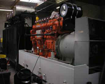
about 2 months. Call / e-mail us for more information or a price quote. See
pictures below of a 900 kW CHP
system that was
custom-built for one of our clients.
"Net Zero Energy Revenues to Reach
$690 Billion by 2020
and
$1.3 Trillion by 2035"
~ Navigant Research
"Net Zero Energy Buildings Are Coming -
What About The Buildings Already Standing?"
~ Forbes
"Net Zero Energy Buildings Are Next Frontier"
~ Sustainable Business
Net
Zero Energy Buildings Are Next Frontier
http://www.sustainablebusiness.com/index.cfm/go/news.display/id/23361
Net
Zero Energy Market to Become $1.3 Trillion/year Industry by 2035
http://www.navigantresearch.com/newsroom/revenue-from-net-zero-energy-buildings-to-reach-1-3-trillion-by-2035
Net Zero Energy Buildings Are Coming - What About The Buildings Already
Standing?
http://www.forbes.com/sites/justingerdes/2012/02/28/net-zero-energy-buildings-are-coming-what-about-the-buildings-already-standing/
"Annual Worldwide Revenues from Frequency Regulation
Services Will Surpass $27 Billion by 2022." ~ Pike Research
http://www.pikeresearch.com/newsroom/annual-worldwide-revenues-from-frequency-regulation-services-will-surpass-27-billion-by-2022
"Changing the Way the
World Makes and Uses Energy" sm

advertising@FlywheelEnergyStorage.com
More
About Flywheel Energy Storage
Flywheel
Energy Storage Project Overview
This
project demonstrates a Flywheel
Energy Storage system designed to respond to a regional transmission
operator signal to quickly add or subtract power from the grid in a frequency
regulation support mode. Using this concept, the flywheel recycles energy (store
energy when generation exceeds loads; discharge energy when load exceeds
generation) instead of trying to constantly adjust generator output.
The
Purpose of the
Flywheel
Energy Storage Project
This
project is being sponsored to determine the relative benefits of having faster
responding generation resources. Additionally, understanding the response time
of a flywheel storage system as compared to traditional generator response time
will provide a better determination of the required sizing for
flywheel and other fast response systems.
When
aggregated to reach appropriate output/input levels there are many benefits that
a flywheel energy storage can offer to the electric grid. The primary benefits
are:
-
Increased
Available energy: Because present day generators need to be operated below
their maximum capability to provide regulation, they are not available to
provide their maximum power. Typically generators need to be below their
maximum capacity by 2 times the amount of regulation in order to provide
headroom for safe operation. If all regulation were accomplished by Flywheel
Energy Storage system, then there would be an additional 2-4 %
generation capacity without adding new generators.
-
Support
onsite
power generation and decentralized
energy
projects with Local Voltage Support: Several Projects have already shown the
benefits of using flywheels for local voltage support. This includes a
project on the NY City transit system, where ten 1.6 KWh flywheels provide
support between train stations. As flywheel storage increases, as will be
demonstrated by this project, the feasibility of larger scale application of
Flywheel
Energy Storage system for local voltage support will be more practical.
Flywheel Energy Storage diagram courtesy of Dept of Energy
The
Flywheel
Energy Storage system consists of an array of flywheel energy storage modules and power
conversion electronics packaged in a standard 12’ x 40’ shipping container.
This mobile container would interface with the grid’s three-phase 480-volt
cables via a step up transformer. This matrix is capable of storing and
recycling 250 kWh’s of energy. The rated discharge rate of a matrix is 1 MW
therefore each container will provide rated power for 15 minutes or lower power
for an extended period.
Monitoring
and data acquisition has been specified such that system availability and
power/energy parameters will be accessible via the website. Any time the system
is operated, the kilowatts supplied or absorbed by the storage unit and the
total system efficiency will be viewable via graphical display by day, week,
month, etc.
While
performing Frequency Regulation,
the Flywheel
Energy Storage system will receive two input signals from the System Operator.
-
Regulation
Signal (RS): This will be the amount of regulation to be provided over the
next time step. This value will be between (-)100KW and (+) 100KW. Minus
refers to absorbing 100kW of power from the Grid. Plus refers to injecting
100 kW of power to the grid. The regulation signal refers to the amount of
power being absorbed or injected relative to a base set point as described
by signal 2. The amount of power being injected or absorbed will be as
measured downstream of the Flywheel
Energy Storage system and upstream of the step up transformer. This
regulation signal will be updated every 4 seconds.
-
Set
Point (SP): This will be the nominal level of power being removed from the
grid during the time on regulation. It will be a percentage of the full
regulation signal and will be a variable during the demonstration phase of
testing. This setting will remain constant over an agreed to time period –
usually one to 24 hours. In addition to the set point and regulation signal
the master controller will have input from the flywheel controller to know
how much energy is in each flywheel. The system controller will then send a
signal to the flywheel controllers, and load bank to control the power flow
within and to and from the Flywheel
Energy Storage system based on these inputs.
The
system will be installed and demonstrated at a location in California. It will be run for a period of six months to demonstrate its ability
to interface with the ISO signals and grid. Data will be independently collected
through funding provided by the U.S. DOE and used to estimate the system
performance over time.
The
Flywheel
Energy Storage system will follow the regulation signal within a fraction of a percent. Unlike
generation based Frequency
Regulation, no fuel is consumed, and no emissions are generated. Analysis of
presently used Frequency
Regulation signals indicates that an energy storage module, which can store or deliver 1 MW
for 15 minutes, would provide regulation services superior to services currently
provided by generators. After development testing is completed the Flywheel
Energy Storage system and will be commissioned and put on automatic control.
What is Battery Energy
Storage?
Battery
Energy Storage, and Battery
Energy Storage systems, use stored electrical power in batteries, and feed
this energy to the electric grid (building, or facility) at times when it makes
economic sense. For a "Net Zero
Energy" building or facility, a Solar
Cogeneration, or Solar
Trigeneration
energy system is used that stores excess solar power in the
Battery
Energy Storage system during the daytime, for use when the sun goes down,
and during inclement weather.
What is Frequency Regulation?
The
electric grid, because supply and demand of electricity is always changing requires
continuous and instantaneous balancing of supply and demand of electricity –
this continuous and instantaneous balancing of supply and demand of electricity
is known as "frequency regulation."
What is "Power Factor" and "Power
Factor Correction?"
Power
factor is a measure of how efficiently, or inefficiently, that electrical power
is used by a customer. For industrial customers, a low power factor is generally
caused by inductive loads such as transformers, electric motors and
high-intensity discharge lighting. Customers that do not use electrical power
efficiently are being charged additional fees for the inefficient use of power
by their electric utility company.
An
electric utility's power load on an electrical distribution system fall into one
of three categories; resistive, inductive or capacitive. In most industrial
facilities, the most common power usages are "inductive."
Examples of inductive loads include transformers, fluorescent lighting and AC
induction motors. Most inductive loads use a conductive coil winding to produce
an electromagnetic field which permits the motor to function.
All
inductive loads require two different types of power for the motor to operate:
Active power (measured in kW or kilowatts) - this power produces the motive
force
Reactive power (kvar) - this energizes the magnetic field of the motor.
The operating power from the distribution system is composed of both active
(working) and reactive (non-working) elements. The active power does useful work
in driving the motor whereas the reactive power only provides the magnetic
field. Unfortunately, electric utility's customers are charged for both active
and reactive power.
Example: A customer's power factor drops, the system becomes less
efficient. A drop from 1.0 to 0.9 results in 15% more current
being required for the same load. A power factor of 0.7 requires approximately
40% more current; and a power factor of 0.5 requires approximately 100% (twice
as much) to handle the same load. The answer to these problems is to reduce
the reactive power drawn from the supply by improving the power factor.
If an AC motor were 100% efficient it would consume only active power. However,
since most AC motors are only 75% to 80% efficient, they operate at a lower
power factor. This means inefficient and even "wasteful" energy usage
and cost efficiency because most electric utilities charge penalties for poor,
inefficient power factor.
Simply installing capacitors will improve a commercial or industrial company's
power factor and will result in savings on their electricity bill every month!
Additional potential benefits for correcting poor power factor include:
Reduction of heating losses in transformers and distribution equipment
Longer equipment life
Stabilized voltage levels
Increased capacity of your existing system and equipment
Improved profitability
Lowered expenses
Some of the information above from the DOE.gov
with permission
"Changing the Way the
World Makes and Uses Energy" sm
advertising@FlywheelEnergyStorage.com
Architecture, Engineering,
Net Zero Energy & Solar Energy Systems
for Commercial, Industrial & Utility Customers
Battery
Energy Storage *
Bulk
Energy Storage
* Clean
Power Generation * Compressed
Air Energy Storage
Cogeneration *
Demand
Side Management
* Distributed
Energy Resources * Dispatchable
Wind * EcoGeneration
Emissions
Abatement * Energy
Master Planning
* Frequency
Regulation * Molten
Salt Storage *
Net
Zero Energy
Peak
Shifting * Power
Purchase Agreements
* Pumped
Hydro Storage *
Rooftop
PV * Solar
Cogeneration
Solar
Thermal Systems *
Solar
Trigeneration *
Trigeneration
* Waste
Heat Recovery
About
us:
The
founder of the Renewable Energy Institute (REI) was first involved in Net
Zero Energy buildings and Solar
Trigeneration sm energy
system in 2001 - 2002. This started with family-owned real estate
developments in Northern and Southern California. This interest was
accelerated when REI's founder was introduced to the President of a solar
company in Los Angeles and their client, the Audubon Nature Center at Deb's Park
(Los Angeles) that was planning to build a new 5,000 sf office and conference
center. Except, the new building for the Audubon Nature Center was about 1/2
mile from the end of the power lines and a very costly extension of the power
lines to their new facility forced them to consider a solar solution. When the
Audubon Nature Center's new 5,000 sf office and conference center was completed
in 2003, the facility not only featured the Solar
Trigeneration sm energy
system - they were awarded one of the first Platinum LEED Awards by the USGBC -
and the powerlines were still 1/2 mile away! To this day, 100% of the power and
energy for the Audubon Nature Center's building is supplied by the Solar
Trigeneration sm energy
system - whether at 12 noon, or 12 midnite. (The Audubon's facility also
includes a battery
energy storage system for back-up power
generated by the Rooftop
PV panels as well as a thermal energy storage
system that stores the excess hot water generated by the evacuated
tube collectors).
These
early projects led to more client inquiries and engagements with real estate
developers, architects and building owners in Southern California, Louisiana and
Texas and the advent of a growing Net
Zero Energy industry along with Solar
Cogeneration sm &
Solar
Trigeneration sm
energy systems. This culminated in a family-owned 200
(Net
Zero Energy) home
real estate development in Desert Hot Springs which has been approved but not
yet constructed.
During
this time, the REI's Founder became a volunteer and Advisor to the University of
Texas' Solar Decathlon Competition. He coordinated the donation of the same solar
thermal system used
at the Audubon Nature Center's facility in Los Angeles, for UT's entry in the
2002 Solar Decathlon Competition in Washington, D.C. UT's entry in the
Solar Decathlon Competition placed 1st in the domestic
hot water competition
that year (2002) and 4th overall, out of 20 universities that had entered.
In
2006, after Hurricane Kattrina devastated New Orleans, the REI was formed and
several of the REI's board members and a Professor from the University of Texas
School of Architecture formed a design team to enter the Brad Pitt/Global Green
Rebuild New Orleans Competition. Our entry also focused on sustainable
building solutions and materials as well as the Net
Zero Energy concepts, incorporating once again, a Solar
Trigeneration sm
energy system.
Today,
the REI "Flagship" has chartered the Renewable Energy Institute in
Florida, with discussions to open REI state chapters in Arizona, California,
Hawaii, Minnesota and Oregon.
The
REI supports greater use of Net Zero Energy systems by architects, builders,
homeowners and owners of commercial buildings. This includes
"upgrading" homes and commercial buildings to Net Zero Energy.
The REI provides Net Zero Energy; advertising, business development,
conferences, e-commerce, education, marketing, online marketing, public
relations, renewable energy, sales and strategic marketing solutions for
architects, builders, cities, colleges, HVAC contractors, Net Zero Energy
developers, real estate developers and universities.
"Changing the Way the
World Makes and Uses Energy" sm
advertising@FlywheelEnergyStorage.com
\
CHP
Systems
* EcoGeneration
* Energy
Master Planning
* Net
Zero Energy
Pressure
to Power
* Solar
Cogeneration
* Trigeneration
* Waste
Heat Recovery
We
deliver solutions:
Advertising
Business
Development
Clean Air
Clean Water
Engineering
Environmental
Health
Marketing
strategies
Investor Relations
Public
Relations
Safety
Sales
plans
Three P's
That produce results for
our Clients:
Increased
sales
New
customers
Greater
market share
Competitive advantage
Increased
shareholder value
People, Planet & Profits
American Energy Plan
sm
www.AmericanEnergyPlan.com
3-5 million new jobs
Fuel Savings of > $1.50/gallon
American Energy Independence
Ends the worst economic depression of all time

“spending
hundreds and hundreds and hundreds of billions of dollars every year for oil,
much of it from the Middle East, is just about the single stupidest thing that
modern society could possibly do. It’s very difficult to think of anything
more idiotic than that.”
~ R. James Woolsey, Jr., former
Director of the CIA
According to R. James Woolsey, for Director of the Central Intelligence Agency, “The basic insight is to realize that global warming, the geopolitics of oil, and warfare in the Persian Gulf are not separate problems — they are aspects of a single problem, the West’s dependence on oil."
We
support the Renewable Energy
Institute and the American
Energy Plan by donating a portion of our profits to the
Renewable Energy
Institute in their efforts to reduce fossil fuel use through
renewable energy and their goals to end fossil fuel pollution by
reducing/eliminating Carbon Emissions,
Carbon Dioxide Emissions and
Greenhouse Gas Emissions.
The
Renewable Energy
Institute
is "Changing The Way The World Makes
and Uses Energy by
Providing Research & Development, Funding and Resources That Creates
Sustainable Energy via 'Carbon Free
Energy,' 'Clean
Power Generation' and 'Pollution Free
Power' Through
Expanding the use of Renewable Energy
Technologies."
#Flywheel #FlywheelEnergy
#Energy #EnergyStorage #FlywheelEnergyStorage


"Changing the Way the
World Makes and Uses Energy"
Flywheel Energy Storage
www.FlywheelEnergyStorage.com
advertising@FlywheelEnergyStorage.com
FlywheelEnergyStorage.com
Copyright © 2007
All Rights Reserved